

I - Motivation
Oh, ARM! It’s time for ARM to shine too. ARM is a famous computer architecture that I learned about in my second year at the university. But why am I talking about ARM? Well, there are situations where my trusty decompiler can’t do its job properly. That’s when obfuscation comes into play, making things more complicated. This is where your expertise in understanding ARM assembly language becomes important, just like we did with Intel in previous chapters. We’ll take the same steps to understand ARM. So, stay focused and stick around cuz it’s fascinating how the ARM architecture has found its way into various devices and platforms since it’s widely adopted in many different products, including MP3 players, iPhones, iPads, Windows phones, and numerous other smartphones. In fact, it has become the primary CPU architecture used for executing instructions in these devices. What’s more interesting if you have read the previous chapter, is that the native lib is basically written using this language so that might be another reason to learn more about it. In this Part, i will be sharing everything i have learned with ARM and try to present them in a funny way.
II - General Idea About ARM
Firstly, it’s important to note that ARM is an example of a RISC (Reduced Instruction Set Computer) architecture, which is different from Intel’s architecture. Now, let’s dive into what RISC and CISC architectures mean. It’s really simple, Imagine you have a toy robot that follows your instructions to do different tasks. Now, let’s think about how you give those instructions to the robot.
In the RISC world, you use simple and straightforward instructions. Each instruction tells the robot to do only one small thing. It’s like giving the robot a single step to follow. For example, you might say, “Take one step forward,” or “Turn left 90 degrees.” These simple instructions make it easier for the robot to understand and execute them quickly. The RISC robot knows only a few basic instructions, but it can do them very fast. On the other hand, in the CISC world, you use more complex instructions that tell the robot to do many things at once. It’s like giving the robot a bunch of steps to follow in a single instruction. For example, you might say, “Walk forward, turn left, and pick up the object.” These instructions are longer and more detailed. The CISC robot can do more things in one instruction, but it might take a bit longer to understand and perform them.
So, to just to summarize:
- RISC: The robot follows simple instructions, one step at a time. It knows a few basic instructions and can do them quickly.
- CISC: The robot follows more complex instructions with multiple steps. It can do more things in one instruction, but it might take a bit longer to understand and perform them.
In real life, computers have processors that work similarly. RISC and CISC are two different ways of designing those processors, where RISC focuses on simple instructions, and CISC focuses on more complex instructions.
So, picture this: ARM instruction set may be smaller compared to x86, but it has a fantastic trick up its sleeve – more general-purpose registers! It’s like having extra pockets to store cool gadgets. And hey, ARM instructions have a fixed width, either 16 bits or 32 bits, depending on the state. In contrast, x86 instructions are like a box of surprises, with varying lengths. You never know what you’ll get! Now, let’s dive into memory access with ARM. It follows a load-store model, which means data needs to be invited from memory into registers before they can join the party. Only special guests called load and store instructions have direct access to memory. Imagine hosting a gathering for your 32-bit value at a specific memory address. In ARM, you’d need to invite it to a register, have some fun with it (like incrementing it), and then send it back to memory. But hey, x86 is a bit more lenient – most instructions can mingle directly with data in memory. It’s like having a party right where the action is! Now, let’s talk about the VIPs of privilege – ARM’s different modes. Brace yourself for a lineup of eight cool modes! You’ve got User (USR), Fast interrupt request (FIQ), Interrupt request (IRQ), Supervisor (SVC), Monitor (MON), Abort (ABT), Undefined (UND), and System (SYS). Each mode has its own privileges and special registers. Think of it like having different levels of access at a theme park. USR mode is like enjoying the rides with basic access, while SVC mode is your all-access pass, similar to ring 0 in x86. It’s where the real VIPs hang out! Most operating systems, like Windows and Linux, create a kernel mode in SVC and a user mode in USR. They know how to throw a good party! Oh, but wait! ARM processors have a secret identity crisis too, just like our beloved x64 processors. They can operate in two states: ARM and Thumb. The state determines the instruction set used, but it doesn’t mess with the privilege level. For example, picture code running in SVC mode, rocking either ARM or Thumb mode. In ARM state, instructions are always 32 bits wide, like super-sized power-ups. But in Thumb state, instructions can be either 16 bits or 32 bits wide. It’s like having different-sized Lego bricks for building code masterpieces. The processor’s state depends on sneaky conditions like branching instructions (BX and BLX) and the T bit in the current program status register (CPSR). At boot-up, ARM cores usually start in ARM state, dancing to their own rhythm until they decide to switch to Thumb state. In recent times, operating systems have been crushing on Thumb code for its higher code density. Mixing 16-bit and 32-bit instructions is like fitting a whole lot of fun into a smaller space. But hey, applications can groove in whichever mode they prefer – it’s their party after all!
So, guess what? ARM architecture has this cool thing called conditional execution. It’s like giving instructions a secret code they have to crack before they can execute. Imagine an instruction saying, “Hey, I’ll only work if the previous instruction’s result is zero!” It’s like a sneaky detective game for instructions. But hold on, x86 is like, “Nah, I execute everything no matter what!” (Well, Intel has a couple of instructions that support conditional execution, but let’s not digress.). Now, why is conditional execution so awesome? It’s like a magic wand that reduces the need for those big, bad branch instructions that can slow things down. They’re like the heavyweight champions of instructions, super expensive! Plus, conditional execution also makes your code more compact. You know, fewer instructions to execute means higher code density. It’s like fitting more fun stuff into a smaller space. But here’s the twist: in ARM state, all instructions are like unconditional party animals by default. They don’t care about conditions. But wait, in Thumb state, we need a special instruction called IT to unleash the power of conditional execution. It’s like the key that opens the door to the land of conditional awesomeness. Now, let me tell you about another funky feature of ARM: the barrel shifter. Picture this, certain instructions can actually “contain” another arithmetic instruction that shifts or rotates a register. It’s like an instruction within an instruction, mind-blowing, right? This trick is super handy because it squeezes multiple instructions into a single one. For example, multiplying a register by 4 and storing the result in another register usually takes two separate instructions. But with the barrel shifter, we can do it in one swift move! Just slide that multiplication (shift left by 2) right into the MOV instruction. Boom! Efficiency level unlocked! So, my friend, ARM architecture is not only powerful but also has some really cool tricks up its sleeve. Conditional execution adds a bit of mystery to the instructions, and the barrel shifter lets us merge instructions like a magician performing mind-bending tricks.
Here’s an example :
1 | MOV R1, R0, LSL #2 ; R1 = R0 * 4 |
III - Data Types and Registers
ARM allows you to perform operations on different types of data. These data types come in different sizes, such as byte, half-word, word, and double-word. It’s like having different-sized treasure chests to hold your valuable loot xD. As you dive deeper into this exciting realm, you’ll encounter sixteen special registers known as general-purpose registers. These registers, named R0, R1, R2, and so on up to R15, are your trusty companions in your ARM adventures. Think of them as magical containers that can store and manipulate your treasures. Among these registers, the first twelve are like your versatile tools—perfect for general use, just like the tools EAX, EBX, and others you might be familiar with in the x86 world. They allow you to perform all sorts of tasks with your loot.
But wait, there’s more! The last three registers have special powers in the ARM architecture:
R13: known as the stack pointer (SP), is like a compass guiding you to the top of the program stack. It shows you where all your previous discoveries and treasures are stored.
R14: the link register (LR), is your secret passage to smooth navigation. It typically holds the return address during a function call. And guess what? Certain instructions implicitly use this register, just like special hidden paths in your adventure. The magical “BL” instruction, for example, stores the return address in LR before taking you to an exciting destination.
R15: the program counter (PC), your ultimate guide in ARM land. It’s like a treasure map, always showing you the address of the current instruction. In ARM state, the PC points to the current instruction plus 8 (two ARM instructions ahead). In Thumb state, it points to the current instruction plus 4 (two 16-bit Thumb instructions ahead). It’s quite similar to EIP/RIP in x86/x64, but with a twist. Unlike x86/x64 where EIP/RIP always points to the next instruction, in ARM, you can directly read from and write to the PC register. Think of it as holding the key to determine which path your adventure will take next!
Adding more, ARM keeps track of important information about the current execution state using a special register called CPSR (Current Program Status Register). Think of it as a magical book that holds crucial details about what’s happening in the ARM realm. It’s quite similar to the EFLAGS/RFLAG register we may have encountered in x86/x64 chapters. Now, let’s dive deeper into CPSR and its interesting features. Sometimes you might come across the term APSR (Application Program Status Register), which is like a special chapter within CPSR, focusing on specific fields. It’s like having a summary of the important parts of the big book! Inside CPSR, you’ll find a variety of flags, like little flags fluttering in the wind. These flags provide valuable information about the ARM processor’s behavior.
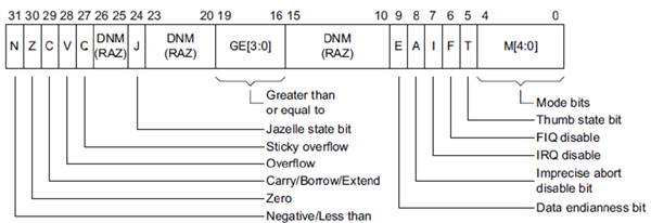
Now, let’s highlight a few exciting flags you’ll encounter in CPSR:
E (Endianness bit): ARM is a versatile architecture that can operate in either big endian or little endian mode. Think of this flag as a switch that determines the byte ordering. When it’s set to 0, it means little endian mode is active, which is commonly used in ARM. It’s like deciding whether you want to read words from left to right or right to left!
T (Thumb bit): This is an intriguing flag that shows whether you’re in Thumb state or ARM state. It’s like a secret doorway between different dimensions of ARM. If the T bit is set, you’re in Thumb state; otherwise, you’re in ARM state. You can even explicitly transition between Thumb and ARM by modifying this bit. It’s like having the power to switch between different magical forms!
M (Mode bits): These bits are like different costumes or disguises that represent the current privilege mode. You can think of them as different roles or characters you can play within the ARM universe. There are various modes, like USR, SVC, and more, each with its own unique set of abilities and privileges.
PS : I will be explaing the rest of them next don’t worry.
IV - Instruction Set
Now, let’s explore some important ARM instructions that will take your understanding to the next level. While ARM shares conditional execution and barrel shifters with other architectures, there are a few unique aspects to its instructions that make it stand out from x86. One fascinating feature is the ability of certain instructions to operate on a range of registers in a sequence. Imagine you have five registers, R6 to R10, and you want to store their values in memory at a specific location pointed to by R1. In ARM assembly, you can accomplish this with the STM (Store Multiple) instruction. You would write something like “STM R1, {R6-R10}”. This magical instruction stores R6 at the memory address in R1, R7 at R1+4, R8 at R1+8, and so on, creating a sequence of stored values. You can even specify nonconsecutive registers by separating them with commas, like “{R1, R5, R8}”. To give a nod to the mystical nature of these ranges, they are typically enclosed in curly brackets in ARM assembly syntax. Another intriguing aspect of ARM instructions is their ability to update the base register after a read/write operation. It’s like having a magical power to modify the very foundation of your actions! This is accomplished by appending an exclamation mark (!) after the register name. For example, if you were to rewrite the previous instruction as “STM R1!, {R6-R10}” and execute it, something extraordinary happens. After storing the values of R6 to R10 in memory, R1 itself will be updated to point to the address immediately after where R10 was stored. It’s like a transformation of the base register, aligning it with the new reality you’ve created!
1 | 01: (gdb) disas main |
In this little scenario, let’s follow the footsteps of a program and observe the mystical transformations that take place. Brace yourself for an enchanting journey! As we dive into the code, we encounter Line 15, where a mesmerizing display awaits us. The value of the Stack Pointer (SP) is revealed to be 0xbedf5848. This is the starting point, the foundation upon which our adventure unfolds. Moving forward to Lines 17 and 19, the air is thick with anticipation. The STM (Store Multiple) instruction is executed, and its magical effects come into play. We witness the power of the instruction as the updated value of SP is revealed. It appears before our eyes, shining with new vitality. Let’s marvel at this wondrous sight! But the spectacle doesn’t end there. We proceed to Line 21, where an extraordinary act occurs. It’s like a grand reveal of treasures. Six magnificent words are dumped, starting from the old value of SP. The magic is in the arrangement: R6 gracefully occupies the old SP, R7 claims its place at SP+0x4, R8 adorns SP+0x8, and R9 finds its spot at SP+0xc. As we hold our breath in anticipation, the illustrious R10 takes its position at SP+0x10. It’s a symphony of registers harmoniously arranged in memory. In this majestic transformation, we witness the birth of a new SP. Like a phoenix rising from the ashes, the new SP emerges at 0xbedf585c. It stands proudly, just after the dwelling place of R10.
V - Loading and Storing Data
AS we have talked in the intro section, ARM is a load-store architecture, which means that data must be loaded into registers before it can be operated on. The only instructions that can touch memory are load and store, all other instructions can operate only on registers. To load means to read data from memory
and save it in a register; to store means to write the content of a register to a memory location. On ARM, the load/store instructions are LDR/STR, LDM/STM, and PUSH/POP.
A - LDR/STR
The syntax may seem complex at first, but i will try to break it down step by step.
Consider this simple example:
1 | 01: 03 68 LDR R3, [R0] ; R3 = *R0 |
In Line 1, we encounter the LDR (Load Register) instruction. It involves a base register (R0) and a destination register (R3). This instruction loads the word value located at the memory address stored in R0 into R3. It’s like plucking a precious gem from the specified memory location and placing it delicately into R3.
On the other hand, Line 2 showcases the STR (Store Register) instruction. Here, R4 serves as the base register, while R3 takes the spotlight as the source of our valuable data. This instruction performs a captivating act: it takes the value stored in R3 and carefully writes it to the memory address specified by R4. It’s like entrusting a cherished treasure to the memory’s safekeeping.
At a fundamental level, LDR and STR instructions rely on a base register and an offset. The offset determines the distance from the base register to the desired memory location. There are three offset forms to consider: immediate, register, and scaled register.
The first offset form employs an immediate value, which is simply an integer. This immediate value is added or subtracted from the base register to access data at a known offset determined during compilation. It’s like taking a measured step forward or backward from the base register to reach the desired memory location.
B - LDM/STM
LDM (Load Multiple) and STM (Store Multiple) instructions are similar to LDR/STR, but with the ability to handle multiple data blocks in a single operation. They are incredibly useful when it comes to efficiently moving sets of data to and from memory. Here’s the general syntax for these instructions:
1 | LDM<mode> Rn[!], {Rm} |
In this syntax, Rn represents the base register, which holds the memory address from where the loading or storing will occur. The exclamation mark (!) is an optional flag that indicates whether the base register should be updated with the new address after the operation (known as writeback).
Rm represents the range of registers to be loaded or stored. This range specifies the set of registers that will be involved in the operation. It can be specified using different forms such as individual registers (e.g., {R0, R1, R2}), consecutive registers (e.g., {R0-R4}), or a combination of both.
There are four modes available for LDM and STM instructions:
IA (Increment After): In this mode, the data is stored starting at the memory location specified by the base address. If writeback is enabled, the base address is updated to point to the address four bytes above the last location stored. This is the default mode if no specific mode is specified.
IB (Increment Before): This mode stores data starting at the memory location four bytes above the base address. If writeback is enabled, the base address is updated to point to the last location stored.
DA (Decrement After): Data is stored in such a way that the last location stored becomes the base address. If writeback is enabled, the base address is updated to point to the address four bytes below the lowest location stored.
DB (Decrement Before): This mode stores data in a way that the last location stored becomes four bytes below the base address. If writeback is enabled, the base address is updated to point to the first location stored.
These different modes provide flexibility in managing the order and direction of data transfer during the loading and storing process which is quite interesting.
Here’s a great example example that I came across in the Practical Reverse Engineering Book:
1 | 01: (gdb) br main |
In Line 9 of the code snippet, we encounter the IA (Increment After) mode with writeback. This means that after the LDM instruction is executed, the base register R6 will be updated with an address that is 4 bytes above the last location accessed, which is represented in Line 23. This pattern of using IA mode with writeback can also be observed in Lines 10, 27, and 30 of the code.
To visualize the effect of these instructions, let’s take a look at picture down, which displays the resulting state after executing the preceding snippet. It provides a clear picture of how the addresses are incremented and how the writeback operation affects the base register R6.
So, as you can see, by using IA mode with writeback, we ensure that the base register is automatically updated with the correct address for subsequent operations, making our data manipulation tasks more efficient and convenient.

C - PUSH and POP
These instructions are quite similar to LDM/STM, but they have two distinct characteristics:
- They implicitly use the Stack Pointer (SP) as the base address.
- The SP is automatically updated during the operation.
Just like in the x86/x64 architecture, the stack in ARM grows downward towards lower memory addresses. The general syntax for PUSH and POP instructions is as follows: PUSH/POP {Rn}, where Rn can represent a range of registers. When we use PUSH, the registers specified in the instruction are stored on the stack in such a way that the last register is placed 4 bytes below the current stack pointer (SP). Additionally, the SP is updated with the address of the first location where the registers are stored.
On the other hand, when we use POP, the registers are loaded from the current stack pointer (SP) onwards. The SP is updated with the address 4 bytes above the last location, indicating the end of the loaded registers. Interestingly, PUSH and POP instructions can be thought of as shorthand for the STMDB (Store Multiple with Decrement Before) and LDMIA (Load Multiple with Increment After) instructions, respectively, with writeback enabled and using SP as the base pointer.
Another Great example from the Practical Reverse Engineering Book, I just can’t get enough of that book a highly recommanded tbh:
1 | 01: (gdb) disas main |
A picture can illustrate the code :
VI - Functions and Function Call
Unlike its intel x86/x64 counterpart, which primarily relies on a single instruction for both function invocation (CALL) and branching (JMP), ARM architecture offers a variety of instructions depending on how the destination is encoded. Let’s dive into the exciting world of ARM function invocation!
When you call a function in ARM, the processor needs to know where to resume execution after the function completes. This location is commonly known as the return address. In x86, the CALL instruction automatically pushes the return address onto the stack before jumping to the target function. Upon completion, the target function resumes execution by popping the return address from the stack into the instruction pointer (EIP).
ARM follows a similar mechanism, but with a few minor differences. First, the return address can be stored either on the stack or in the link register (LR). To resume execution after the function call, the return address is explicitly popped from the stack into the program counter (PC), or an unconditional branch to the LR is executed. Second, a branch instruction can also switch between the ARM and Thumb states, depending on the least significant bit (LSB) of the destination address. Finally, ARM defines a standard calling convention: the first four 32-bit parameters are passed via registers (R0-R3), while the remaining parameters are placed on the stack. The return value from the function is stored in the R0 register.
Now let’s explore the instructions used for function invocations in ARM: B, BX, BL, and BLX.
- The B instruction, although uncommon for function invocations, is used for control transfer in general. It serves as an unconditional branch, similar to the JMP instruction in x86. Typically, B is employed within loops and conditionals to loop back to the beginning or break out of the loop. It can also be used to call a function that never returns. However, it’s important to note that B can only use label offsets as its destination and cannot use registers. In this context, the syntax of B is as follows: B imm, where imm represents an offset relative to the current instruction. It’s worth mentioning that ARM and Thumb instructions are aligned to either 4 bytes or 2 bytes. Consequently, the target offset needs to be an even number to ensure proper alignment.
Here’s an example of the usage of “B” :
1 | loop: |
BX: is the Branch and Exchange instruction in ARM. It shares similarities with the B instruction as it transfers control to a target location. However, BX has the additional capability of switching between ARM and Thumb states. The target address is stored in a register. Instructions ending with “X” indicate the ability to switch states. If the least significant bit (LSB) of the target address is 1, the processor automatically switches to Thumb state; otherwise, it executes in ARM state. The syntax for BX is BX
, where the specified register holds the destination address. The two common uses of BX are returning from a function by branching to the link register (LR) with “BX LR” and transitioning to code in a different mode (e.g., going from ARM to Thumb or vice versa). In compiled code, it is common to see “BX LR” at the end of functions, serving as an equivalent to “RET” in x86. BL: is the Branch with Link instruction in ARM. It shares similarities with the B instruction but additionally stores the return address in the link register (LR) before transferring control to the target offset. This instruction closely resembles the CALL instruction in x86 and is often used for function invocation. The format of BL is the same as B, accepting only offsets as parameters.
Here’s an example of a function invocation and returning :
1 | 01: 00014350 BL foo ; LR = 0x00014354 |
line 1 invokes the function “foo” using BL. Before transferring control to the destination, BL stores the return address (0x00014354) in the link register (LR). The “foo” function performs some operations and returns to the caller using BX LR, which branches back to the address stored in LR.
- BLX: is the Branch with Link and Exchange instruction in ARM. It combines the functionalities of BL and BX, providing the option to switch states. The major difference is that BLX can take either a register or an offset as its branch destination. When BLX uses an offset, the processor always swaps the state (ARM to Thumb or vice versa). BLX is often considered the equivalent of the CALL instruction in x86. In practice, both BL and BLX are used for function calls. BL is typically used when the function is within a 32bit range, while BLX is used when the target range is undetermined, such as with a function pointer. In Thumb state, BLX is commonly used to call library routines, while in ARM state, BL is preferred.
VII - Arithmetic Operations
This part is quite interesting, okay I will try to simplify stuff. Imagine you have a memory full of treasures, and you want to bring them into your magical registers to perform amazing operations. The MOV instruction is like a teleportation spell that allows you to move a treasure from one register to another. You can choose a constant treasure, a treasure from another register, or even a treasure that has been transformed by a mysterious barrel shifter.
But what’s a barrel shifter, you ask? Well, it’s a special device that can twist and turn the treasures, making them more powerful or altering their properties. It can shift them to the left or right, rotate them around, or even give them a magical shake.
For example, you can use the MOV instruction like a magical wand:
1 | 01: 4F F0 0A 00 MOV.W R0, #0xA ; R0 captures the treasure 0xA |
You see, with the barrel shifter’s enchantments, you can modify the treasures to your liking and wield their powers as you wish.
But the fun doesn’t stop there! ARM provides you with a whole arsenal of magical operations. You can add treasures together, subtract them, multiply them, or even combine their hidden bits using logical operations.
Here’s a glimpse of the magical spells you can cast:
1 | 01: 4B 44 ADD R3, R9 ; R3 gains the combined power of R3 and R9 |
Isn’t it fascinating habibi xD? You can unleash the power of these magical instructions and create incredible outcomes. Just remember to keep an eye out for those special flags that indicate the effects of your enchantments. Oh and i almost forgot while ARM doesn’t have a native divide instruction, don’t worry You can always rely on a secret software implementation to perform the division spell when needed.
VIII - Conditional Execution and Branching
Okay, this is an interesting part give me your focus. In the world of assembly programming, things can get more interesting with conditionals and loops. To handle these situations, we have special flags stored in the Application Program Status Register (APSR). These flags help us make decisions and control the flow of our program.
Let’s meet these flags:
- The N (Negative) flag tells us if a result is negative.
- The Z (Zero) flag indicates if a result is zero.
- The C (Carry) flag shows if there was an overflow in an unsigned operation.
- The V (Overflow) flag reveals if there was an overflow in a signed operation.
By checking these flags, we can determine what actions to take next in our program. It’s like having a set of rules that guide us through the code. Simple, right?
So, when you encounter conditionals or loops in your assembly adventure, keep an eye on these flags. They will help you make the right decisions and navigate through the challenges that lie ahead.
Here’s a picture that can illustrate the relation between the APSR and the CPSR :
Another picture of a table that can resume all the conditions of the branching :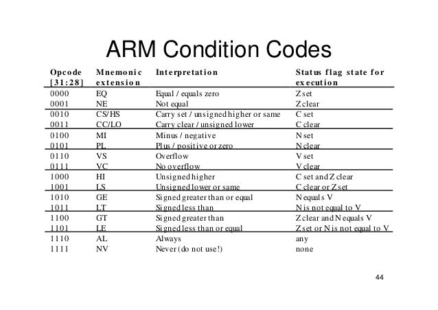
So, if you look at the table for instance, if we have “BLT,” it means “Branch if Less Than.” This is similar to “JL” in x86. The instruction will only branch if the LT condition is true. By default, instructions do not update the conditional flags unless we use the “S” suffix. However, comparison instructions such as CBZ, CMP, TST, CMN, and TEQ automatically update the flags since they are commonly used before branch instructions.
Among these comparison instructions, CMP is quite popular. Its syntax is CMP Rn, X, where Rn represents a register, and X can be an immediate value, a register, or a barrel shift operation. CMP performs the subtraction Rn - X, sets the appropriate flags based on the result, and discards the actual result. Typically, CMP is followed by a conditional branch instruction to make decisions based on the comparison.
Another commonly used comparison instruction called TST. Its syntax is the same as CMP, making it easy to remember. The semantics of TST are similar to the TEST instruction in x86. TST performs a bitwise logical AND operation between Rn and X, sets the appropriate flags based on the result, and discards the actual result.
Typically, TST is used to test whether a value is equal to another value or to check specific flags. Similar to other compare instructions, it is often followed by a conditional branch instruction to perform actions based on the test result.
Here’s an example that illustrates the usage of TST:
1 | TST R1, #0xFF ; Perform bitwise AND between R1 and 0xFF |
In Thumb-2 state, there are two handy comparison instructions: CBZ and CBNZ. These instructions have a straightforward syntax: CBZ/CBNZ Rn, label. Here, Rn represents a register, and label is an offset to branch to if the specified condition is true.
Let’s break down the usage of CBZ and CBNZ with an example:
1 | CBZ R1, null_label ; Branch to null_label if R1 is zero |
In this example, the CBZ instruction checks if the value in register R1 is zero. If it is indeed zero, the program will branch to the null_label. This is often used to test if a number is equal to zero or if a pointer is NULL.
Similarly, we have the CBNZ instruction:
1 | CBNZ R2, non_null_label ; Branch to non_null_label if R2 is not zero |
Apart from the commonly used comparison instructions like CMP and TST, there are two additional comparison instructions in ARM architecture called CMN and TEQ. However, these instructions are not commonly used, so we won’t cover them here.
We have already discussed how the branch instruction (B) can be used for conditional branching by adding a suffix (e.g., BEQ, BLE, BLT, BLS). But did you know that most ARM instructions can also be conditionally executed in a similar manner? If the specified condition is not met, the instruction behaves as a no-op, effectively doing nothing. This instruction-level conditional execution can reduce the need for branches and potentially improve execution time.
Here’s an example to illustrate this concept:
1 | ADDNE R0, R1, R2 ; Add R1 and R2 and store the result in R0 if the NE condition is true |
In this example, the instruction ADDNE adds the values in registers R1 and R2 and stores the result in register R0, but only if the NE (not equal) condition is true. If the NE condition is not met, the ADDNE instruction is effectively skipped, and the program continues to the next instruction.
IX - JIT and SMC
This is the last part of this chapter, there was a concept that we talked about in the previous chapter which is the JIT, it was really interesting looking at it from the ARM perspective so basically ARM architecture offers support for two important concepts such as the just-in-time (JIT) compilation and self-modifying code (SMC). JIT code refers to native code that is dynamically generated by a JIT compiler. For instance, i have read that languages like Microsoft .NET compile to an intermediate language (MSIL) that is then converted into native machine code (such as x86, x64, ARM) for execution on the CPU. On the other hand, SMC involves generating or modifying code during the current instruction stream. A common example of SMC is the use of encoded shellcode that is decoded and executed at runtime. Both JIT and SMC code require writing new data to memory, which is later fetched and executed.
So in the ARM core, there are separate cache lines for instructions (i-cache) and data (d-cache). The i-cache holds instructions that are executed, while memory access is performed through the d-cache. It’s important to note that these cache lines are not always coherent, meaning that data written to one cache may not be immediately visible to the other. For example, if new or modified instructions are written to the d-cache, the i-cache may not be aware of these changes and continue executing outdated instructions. This can result in unpredictable crashes or incorrect results, which is undesirable when working with JIT systems or shellcode. So to solve this issue, it is necessary to explicitly refresh or flush the i-cache to ensure coherency. On ARM, this can be achieved by updating a register in the system control coprocessor (CP15). Here’s an example code snippet that demonstrates this operation:
1 | MOV.W R0, #0 |
In this example, the MOV instruction loads the value 0 into register R0, and then the MCR (Move to Coprocessor Register) instruction updates the system control coprocessor (CP15) to flush the i-cache. It’s worth noting that most operating systems provide interfaces or functions to perform this operation, so typically, you wouldn’t need to implement it yourself. For instance, on Linux, you can use the “__clear_cache” function, while on Windows, you can use “FlushInstructionCache” function to achieve the same effect.
Same ending, don’t hesitate to reach out to me if you have any questions! We’re all on this journey together. You can find me on Discord at @IronByte#0855 | @Ir0nbyte or connect with me on LinkedIn . And hey, make sure to follow me on Twitter too @ir0nbyte . See you in the next journey.